Description of the working principle of the rotary vane vacuum pump
The picture shows the working principle of the rotary vane pump. The rotary vane pump is mainly composed of stator, rotor, rotary vane, fixed cover and spring.
Schematic diagram of the working principle of the rotary vane pump  | 2- rotating piece ; 3- rotor ; 4- spring ; 5- exhaust valve |
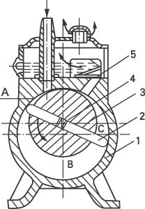
. The structure is such that the rotor eccentrically mounted in the stator cavity (the gap between the outer circle of the rotor and the inner surface of the stator is very small) and the sliding in the rotor groove are closely attached to the inner wall of the stator by spring tension and centrifugal force. The two rotating pieces always slide along the inner wall of the stator as the rotor rotates.
The two rotary vanes divide the crescent-shaped space enclosed by the rotor, the stator inner cavity and the fixed cover into three parts A, B and C. When the rotor rotates in the direction shown, the volume of the space A communicating with the suction port Constantly increasing, the pressure in the A space is continuously reduced. When the pressure in the A space is lower than the pressure in the pumped container, the pumped gas is continuously drawn into the suction chamber A according to the principle of gas pressure balance. At the time of inhalation. The volume of the space of the B cavity is gradually decreasing, the pressure is continuously increasing, and the compression process is being performed at this time. The volume of the space C communicating with the exhaust port is further reduced, and the pressure of the C space is further increased. When the pressure of the gas is stronger than the exhaust pressure, the compressed gas pushes open the exhaust valve, and the exhausted gas continuously The ground passes through the oil layer in the oil tank and is discharged into the atmosphere. During the continuous operation of the pump, the process of inhaling, compressing and exhausting is continuously performed, thereby achieving the purpose of continuous pumping.
The exhaust valve is immersed in the oil to prevent the atmosphere from flowing into the pump. The oil enters the pump chamber through the gap on the pump body, the oil hole and the exhaust valve.
Two-stage rotary vane vacuum pump working principle diagram |
1-Advanced exhaust valve; 2-channel; 3-low exhaust valve |
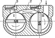
The two-stage rotary vane vacuum pump consists of two working chambers. The two chambers are connected in series before and after, and rotate in the same direction at the same speed. The I chamber is a low vacuum level, the second chamber is a high vacuum level, and the pumped gas enters the chamber II through the air inlet. When the incoming gas pressure is high, the gas is compressed by the chamber II, and the pressure is rapidly increased. The compressed gas is not only discharged from the advanced exhaust valve, but also passes through the middle wall passage, enters the I chamber, is compressed in the I chamber, and is discharged from the lower chamber. The gas valve is discharged; when the pressure of the gas entering the chamber II is low, although the compression of the chamber II is performed, the advanced exhaust valve cannot be pushed out, and the gas enters the I chamber through the middle wall passage, and continues to be compressed by the chamber I, The low-grade exhaust valve is discharged, so the two-stage rotary vane vacuum pump has a higher ultimate vacuum than the single-stage rotary vane vacuum pump.
White PS 18 tubular glass vaccine vials blister trays ampoule
Blister Tray,Plastic Blister Tray,blister tray packaging,Ps Glass Vaccine Blister Tray
taicang hexiang packaging material co.,ltd , https://www.medpackhexiang.com